Creating a custom 3d-printed fallout themed clock with backlighting – Assembly Guide
This is a guide to build your own fallout themed 3d-printed clock.
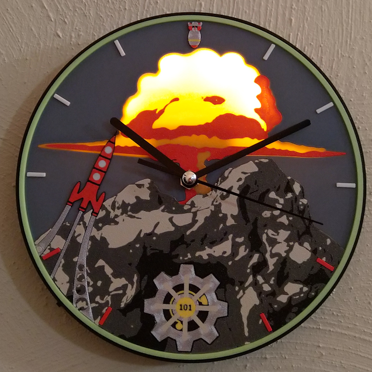
It is meant for printing and assembling the files I from my cults page CULTS into an awesome backlit clock. However the principles here apply to any custom clock you might want to create with 3d printing and or led backlighting.
The Clock size: 210.1 x 210.1 x 24.1 mm (X Y Z).
So at least a 22cm buildplate is recommended for printing.
I will explain how to:
- 3D print flat artworks
- Assemble them into an artwork
- Solder a LED circuit with on/off switch
- Add the actual clockwork
Here is a list of needed pieces, they are listed again in the respective section with links to the pieces i used:
- The stl files for 3d printing are on cults3d: here
- and enough filament colors to make the artworks (or you can paint them theoretically by hand after printing. Though that might ruin the lighting effect.)
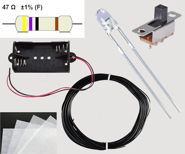
- 4x 3mm orange LEDs (2V, 20mA)
- 4x 47 Ohm resistors
- 1x Miniature slide switch
- Wire/Cable (isolated)
- Holder for 2 AA batteries with connection cable
- A piece of white parchment paper (uncoated)
- 1 Clockwork (8mm shaft, with at least 3,4mm shaft height)
- 3x AA Batteries
Equipment for assembly:
- Soldering Kit
- superglue
- hot glue
- small wrench (for the clockwork )
I used a Bambu X1C and the Bambulab Studio Slicer for this project.
3D Printing the Parts
First of all the colors have to be decided. The exact look of the artwork depends on them. These tables show the filaments and colors I used, where to get them and maybe a note about my usage of them. There is not necessarily a reason for those exact filaments or manufacturers and any preferred color can be used. All filaments used are PLA!
There are 6 artwork prints in total, including the background. They make up the clock face.
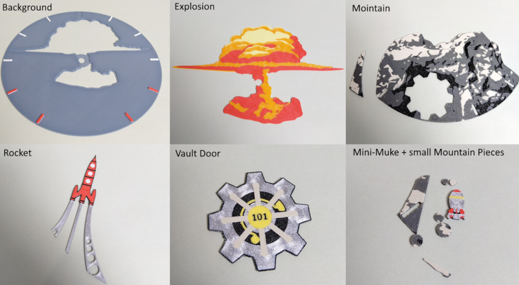
Background:
| Artwork-Color | Filament Used | Note |
| Blue Grey | PLA Basic Blue Grey : Bambulab | |
| White | PLA White : Sunlu https://amzn.to/3H1g53m | |
| Red | PLA NX-2 Hellfire-Red : Extrudr https://amzn.to/3NMF4v7 |
Explosion:
| Light Yellow | PLA Lemon Yellow : Sunlu https://amzn.to/47g98X4 |
| Orange | PLA NX-2 Orange : Extrudr https://amzn.to/47pB9LW |
| Red | PLA NX-2 Hellfire-Red : Extrudr https://amzn.to/3NMF4v7 |
Mountain:
| Light Grey | PLA NX-2 Grau : Extrudr https://amzn.to/3NJuzbP | |
| Grey | PLA Grey : Sunlu https://amzn.to/3S04GqS | A lighter Grey tone would be better as this is barely visible and almost as dark as the Anthrazit. But i didn’t find one. |
| Dark Grey | PLA NX-2 Anthrazit : Extrudr https://amzn.to/3S14doz | |
| Black | PLA Black : Sunlu https://amzn.to/47bUoIE |
Vault Door:
| Yellow | PLA Basic Yellow : Bambu |
| Metall | PLA Silk Silver : Sunlu https://amzn.to/48dBbHD |
| Light Grey | PLA NX-2 Grau : Extrudr https://amzn.to/3NJuzbP |
| Black | PLA Black : Sunlu https://amzn.to/47bUoIE |
Rocket:
| Red | PLA NX-2 Hellfire-Red : Extrudr https://amzn.to/3NMF4v7 |
| Black | PLA Black : Sunlu https://amzn.to/47bUoIE |
| Metall | PLA Silk Silver : Sunlu https://amzn.to/48dBbHD |
| White | PLA White : Sunlu https://amzn.to/3H1g53m |
Mini-Nuke:
| Metall | PLA Silk Silver : Sunlu https://amzn.to/48dBbHD | Here I would recommend darker silk filament like the Extrudr metallic grey https://amzn.to/3TGKL1y |
| Red | PLA NX-2 Hellfire-Red : Extrudr https://amzn.to/3NMF4v7 | |
| Yellow | PLA Basic Yellow : Bambu |
Clock Frame:

The clock frame can be printed mono-black or you can add a color accent to the inner ring. I used glow in the dark neon green.
| Black | PLA Black : Sunlu https://amzn.to/47bUoIE |
| Neon Green | PLA Glow Green : Bambu |
The print settings and print files are explained in the following. The settings here refer to the Bambulab Slicer but most settings are available in every commonly used slicer and if not they probably can be ignored.
There are two methods to print the artworks and for both the relevant files exist.
- They are printed with a multicolor printer, printing the color within the same layer
- They are printed with a different color on the layers, stacking different colors at different parts, resulting in more height.
For my personal clock I used the first method and printed on the Bambu X1C with AMS.
All files are from my Cults page: https://cults3d.com/en/3d-model/home/fallout-themed-wall-clock-with-backlighting
Printing Color in the same Layer
For printing the color in the same layer, the files in the directory “Multicolor_sameLayer_Clock” are used.
(Skip to section “Printing Color with Layer Heights” if you want to print the color via layer height)
Import into the slicer
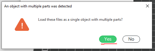
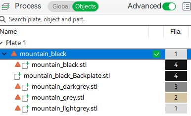
Every artwork and the clock frame are objects with multiple parts and all the parts of one object are within the same directory. Select all drag and drop them into the slicer as an “object with multiple parts”.
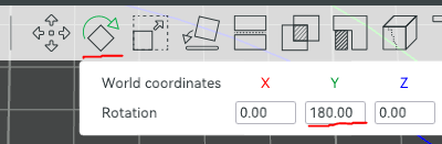
Then you want to select all parts and rotate them around 180° on the Y-axis. This way you have a smooth or a nicely textured surface depending on the print plate. Either way it’s a smoother finish than nothing or ironing it.
Next color each part with the respective color. By changing the filament for the selected part. This is done in the “objects” tab under the “process” section on the left. The color of every part is given in the filename for orientation.
You can ignore the warnings about non-manifold edges. The slicer can handle it when slicing.
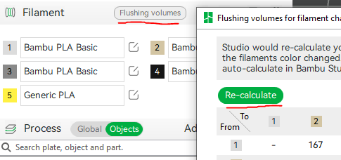
Finally recalculate the flushing volume to make sure no single color is contaminated with another.
Print Settings
These additional settings helped me get a good print for the artworks:
- Layer Height 0.2mm
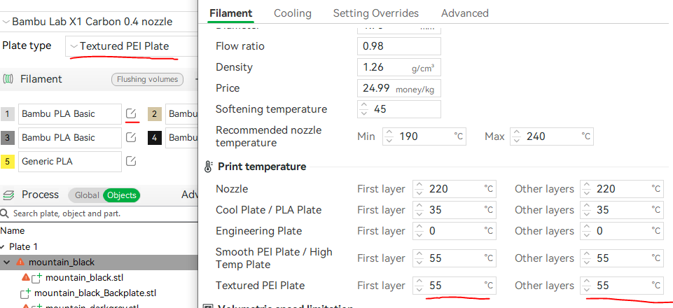
- Increase Plate Heat by About 5°C to avoid warping. This is in the filament settings in the bambulab slicer. Make sure to select the filament setting for every color and to set the heat for your selected print plate.
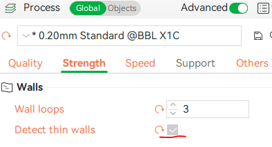
- Activate „Detect Thin Walls“ to allow for very thin walls with only one line of width between artwork lines.

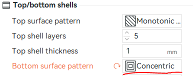
- Concentric pattern for the first layer. This helped me get a better result on the first layer.

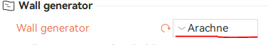
- Wall Generator: Arachne, with default settings. To better fill weirdly shaped spaces.

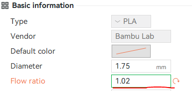
- Increase Filament flow ratio to 1,02mm (from default 0.98mm). This depends on your filament and may be different for you. But generally a slightly higher ratio helps to fill spaces between lines. This is also in the filament settings. Make sure to select the filament setting for every color.

Specifics
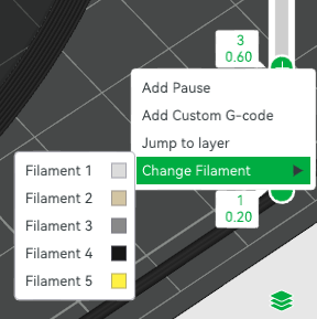
- The clock background has its colors added by layer change at certain heights. Start with black as color to decrease the light shining through the background! Change to blue grey at layer 3, to white at layer 8 and to red at layer 13 (using 0.2mm layer height). The setting is found in the review by right clicking the “+” on the side bar.

- The clock frame can be printed in black only, or you give the inner ring a separate color. It is its own part of the same object. Alternatively the inner ring can be printed on its own and glued in. In that case use the ring “ClockFrame_InnerTopRing_seperateObject.stl” which has tolerances added.
- It also requires support below the place where the battery goes! You can add the support to the specific face by using support painting.
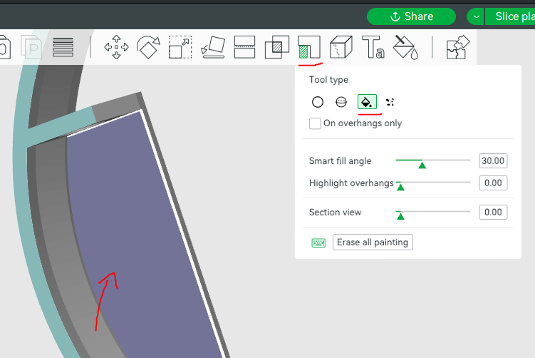
- The LED-Frame also requires support. Auto generated support will do fine. It should be printed in white for better lighting.
If you have trouble with warping in general or parts not sticking to the plate (e.g the small mountain parts), add a brim. I prefer to do it without a brim because it’s not always easily removed without recess.
Printing Color with Layer Heights
(If you have read “Printing Color in the same Layer”:
Skip to „Assembling the Clock Face„)
For printing the color in different layers heights, the files in the directory “color_differentLayer_Clock” are used.
Import into the slicer
- Load the artwork into the slicer
- Set layer height to 0.2mm
- Slice the object and go in preview mode
- Change color: On the right side bar which shows the current layer, right click after every 2 layers and change the filament to the correct color. The order and which color is written in the filename as orientation. E.g. “Rocket_1black-2white-3red-4metall.stl” means: start with black, change to white at layer 3, change to red at layer 5, change to metall at layer 7.
Print Settings
These additional settings helped me get a good print for the artworks:
- Layer Height 0.2mm
- Increase Plate Heat by About 5°C to avoid warping. This is in the filament settings in the bambulab slicer. Make sure to select the filament setting for every color and to set the heat for your selected print plate.

- Activate „Detect Thin Walls“ to allow for very thin walls with only one line of width between artwork lines.
- Concentric pattern for the first layer. This helped me get a better result on the first layer.
- Wall Generator: Arachne, with default settings. To better fill weirdly shaped spaces.
- Increase Filament flow ratio to 1,02mm (from default 0.98mm). This depends on your filament and may be different for you. But generally a slightly higher ratio helps to fill spaces between lines. This is also in the filament settings. Make sure to select the filament setting for every color.
Specifics
- For the clock background, start with black as color to decrease the light shining through the background! Change to blue grey at layer 3, to white at layer 8 and to red at layer 13 (using 0.2mm layer height).
- The clock frame can be printed in black only. For color you can print the inner ring on its own and glued in. In that case use the ring “ClockFrame_InnerTopRing_seperateObject.stl” which has tolerances added.
- It also requires support below the place where the battery goes! You can add the support to the specific face by using support painting.

- The LED-Frame also requires support. Auto generated support will do fine. It should be printed in white for better lighting.

If you have trouble with warping in general or parts not sticking to the plate (e.g the small mountain parts), add a brim. I prefer to do it without a brim because it’s not always easily removed without recess.
If the color is not saturated enough, using 0.1mm layer height might help a bit.
Assembling the Clock Face
Now all the 3D printed parts are assembled into the clock face.
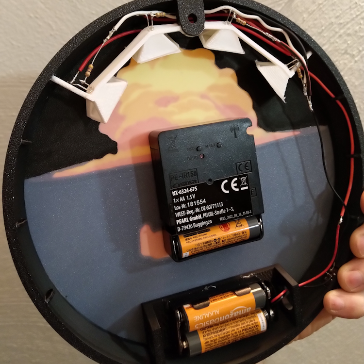
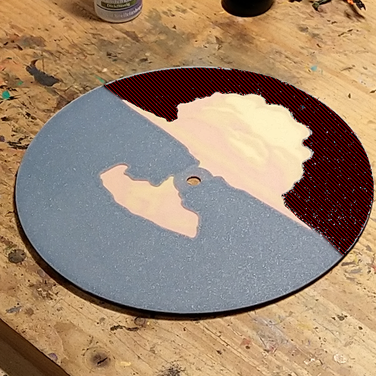
First check how much light shines through your background. If it is too much you might want to paint the backside black around the explosion cutout. Acrylic black paint will do fine. Painting the upper half (as shown in the following image) should be enough as the LEDs shine from top to bottom. But it can lead to slight shine through effects below the explosion.
Now to actually assemble the parts:
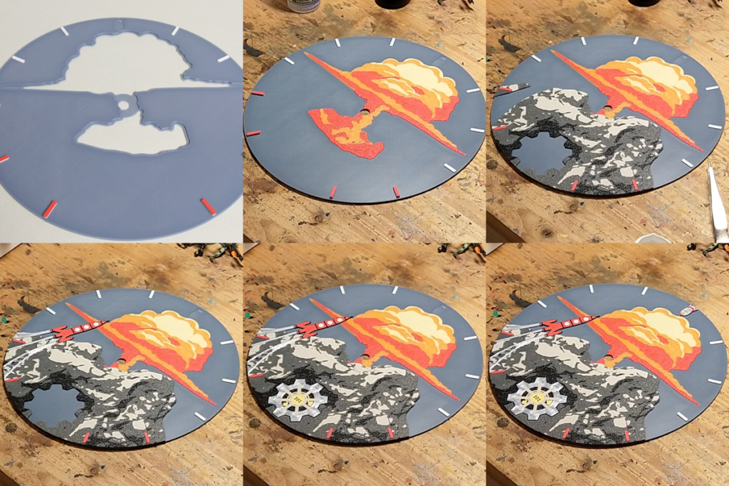
- Place the background on a flat surface and put some superglue around the brim of the explosion cutout. Enough to make a strong bond but not too much not to spill onto the background or out of the brim.
- Place the mountain pieces over the clock ticks, using only a few drops of glue. Except for the explosion which holds the clockwork together with the background, no artworks hold any weight. So a few small drops of glue are enough.
- Glue in the rocket between the mountain pieces, check that it aligns with the border.
- Fill the gaps with the smaller mountain pieces. Putting glue on the background instead of the parts helps to avoid spillage when dropping small parts.
- Add the Vault door into the mountain, it represents the 6 on the clock.
- Add the Mini Nuke, representing the 12. Put glue into the cavity and drop the mini nuke into it.
The Clock Face is now assembled. Before putting it into the Clock frame, the soldering work should be done.
Solder the Electronics
| Needed Parts | Link |
| 4x 3mm orange LEDs (2V, 20mA) | https://amzn.to/3vhAf6E |
| 4x 47 Ohm resistors | https://amzn.to/3viNMuM |
| 1x Miniature slide switch | https://amzn.to/47gFL6M |
| 1x Holder for 2 AA batteries + cable | https://amzn.to/41H4WOX |
| Isolated wire | https://amzn.to/3H16ZUg |
| white parchment paper | https://amzn.to/48uMECu |
| AA Batteries | https://amzn.to/3TNga2t |
Prerequisites
The circuit is a simple parallel setup with every LED in parallel, a resistor in front of them and an added on/off switch. (putting the resistor before or after the LED does not matter):
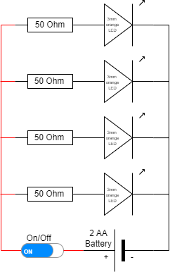
Note if your LEDs require more voltage, you have to reduce the resistor strength.
To calculate the required resistors use the following formula:
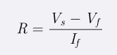
Where “Vs” is your supplied voltage, which is 3V for 2 AA batteries, “Vf” is your needed voltage for your LEDs in my example 2V and “If” is the LEDs current, here 20mA.
Example: (3V – 2V) / 0.02A = 50 Ohm.
In most resistor-sets you have 47 Ohm not 50, but they work just as well and make the LED theoretically a bit brighter. So I used 47 Ohm instead of 50.
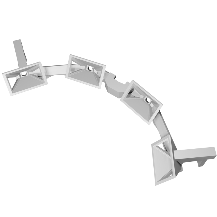
To get started, first of all glue pieces of parchment paper onto the LED Frame. This will scatter the LED light and give a smoother, more uniform and dispersed light. I glued 2 layers of the paper in front of every LED casing:
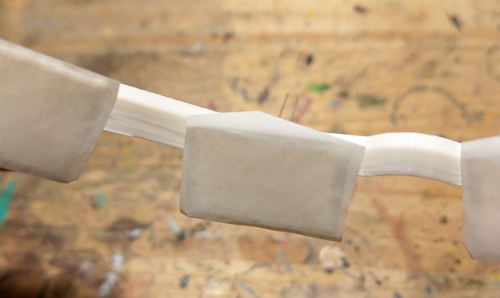
There are LEDs that already provide that effect through a rougher surface like these: https://amzn.to/3H0YcBS , but the ones I found are not as bright as the normal LEDs.
Soldering
These are the steps I took to solder the circuit. Keep in mind you can do it however you like if you keep the same circuitry. It can be done better than what I show here but it works.
Use isolated wire to avoid short circuits!
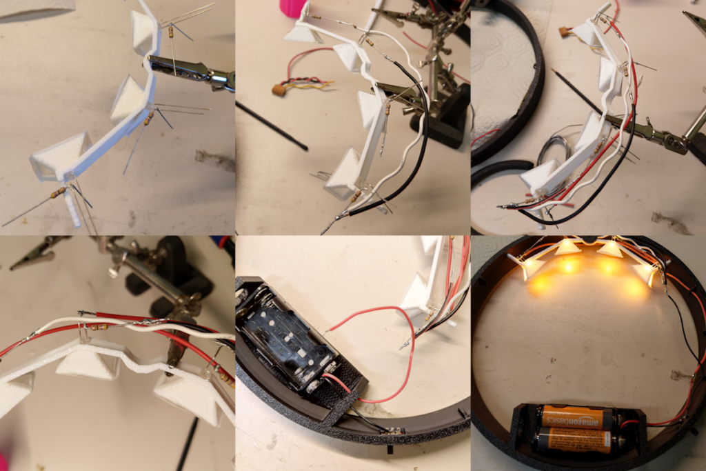
- Take the LED frame with the flat side up
- Stick the LEDs into it (if you have larger LEDs you can always drill larger holes into the frame).
- Make sure they all face the same direction. Negative is the flat side on the LED casing and usually the shorter leg.
- Add the resistors with a 90° bend
- Connect all negative sides to the first LED (I used the resistor as connection point).
- Connect all positive sides from the longer LED leg to the positive side of the first LED (I used the LED leg as connection point).
- Glue in the battery holder with hot glue, superglue or tape
- Glue in the slide switch with super glue into the slit on the right side (if upside down) of the frame.
- Connect them to the circuit
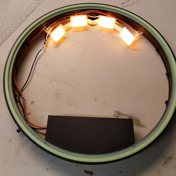
- Insert batteries and check functionality
- Glue the LED frame in place with superglue. It rests on the part with the hole for hanging the clock and the two ends stick into the frame where the cavities are.
Here are some best practices when soldering:
- Perform soldering in a well-ventilated area. Never touch the tip of the soldering iron
- Use the appropriate tip for your soldering iron. The most common tips used in electronics projects are the conical tip.
- Solder Type: Use a lead free solder for electric soldering: https://amzn.to/3TJWrAu
- Cleanliness: Clean wire is extremely important as this can cause adhesion issues. If the wire was corroded, it’s best to cut that back and find a clean section to work with.
- First coat the exposed wires in solder.
- Heat Application: Begin heating the wires by placing the solder gun underneath them. This will take time. Apply solder above wires so the solder is fed to the top and not the bottom.
- Soldering Process: Allow solder to completely coat over the exposed wires, then remove heat and solder. Let the solder cool down without touching helping hands or wires.
- Post-Soldering: Turn off and unplug the soldering iron when not in use.
I prefer using a good soldering kit with a holder and sponge for cleaning (make sure to wet it). Like this one: https://amzn.to/3NK5Vbd

Adding the Clockwork
After Soldering and gluing the LED frame as well as the clock face, place the clock face into the frame.
Make sure the Mini-Nuke (top side) faces the correct side (where the nail hole is). Put super glue around the brim where the face will lie, gently place the clock face into position. Then check the orientation and if everything is aligned correctly, firmly press it down and let it dry.
For the clockwork I decided on a radio controlled, silent clockwork like this one https://amzn.to/3tyJVcw from St. Leonhard.

- Insert the clockwork thread through the hole in the middle of the clock face.
- Orient the battery compartment from the clockwork to face down (to 6 o’clock)
- Screw in the screw nut from the front and tighten it.
- Now lay down the clock face (put something below it if it does not lay flat due to the pin in the clockwork)
- Put in the clock hands starting with the hour, minute then second hand.
- Put them in facing 12 o’clock
- Insert them by pressing down on both sides of the spring cap
- Now remove the pin on the backside!
- Insert batteries
- Let the clock set itself up.
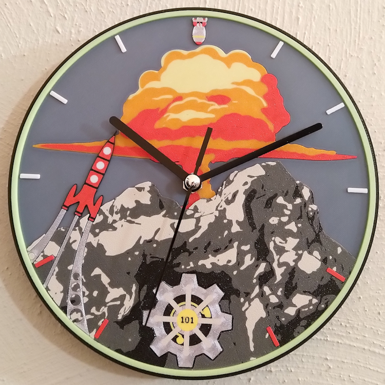
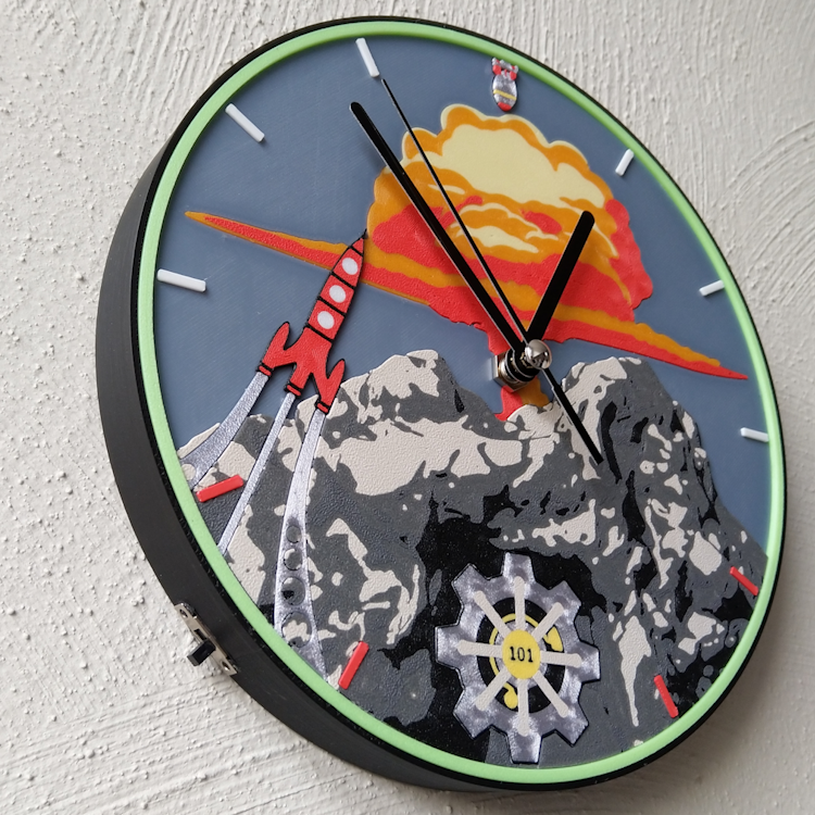
Done the clock is now finished
Here is my clock from the backside, notice the black colored backside of the background to avoid light leakage. The right image shows some slight light leakage on the top of the image which I fixed with a second coat of black paint.